Development of custom electronic boards with CNC Router.
During this week, we had the privilege of delving into the exciting realm of computer-aided design. We explore the modeling process in both 2D and 3D, highlighting the importance of parametric methodology. This approach allowed us to understand the flexibility and efficiency it brings to the creation of designs, providing a comprehensive view of the capabilities of the software in question.
When we talk about 2D modeling, it is advisable to use a raster based program. These programs work with the idea of a rectangular field of pixels, where each small dot represents a fundamental element in the visual composition. When tackling this task, the task is to carefully define both the color and transparency of each pixel, thus providing a detailed and versatile platform for the creation of two dimensional images. This pixelated approach not only allows for precise creative expression, but also offers a wide range of possibilities to bring your ideas to life in the realm of 2D design, Typical programs are mentioned below:
Based on my experience with the programs mentioned, I have not had the opportunity to use GIMP. Therefore, I want to carry out the process with this software so that I can explore it and thus better understand the different capabilities and advantages of each of the mentioned programs.
However, there is the alternative of generating images by using vector-based programs. This approach is differentiated by working with geometric entities, such as lines and curves, defined by their mathematical properties. This makes it easier to create scalable and editable illustrations, offering a different perspective compared to raster-based modeling.
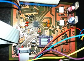
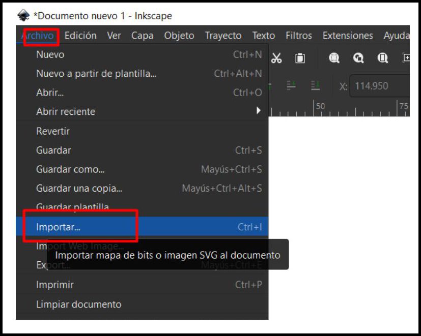
Once inside the GIMP software working environment, you proceed to import the image you want to edit and rasterize.
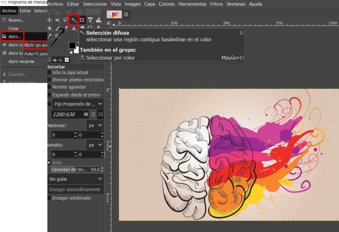
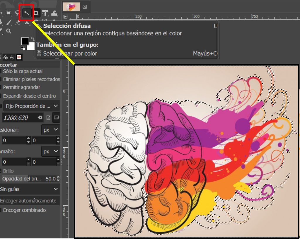
Once the image has been imported, the next step is to select the Fuzzy selection tool. This tool will do most of the work and is extremely versatile. Simply click on the region we want to remove the background from, and the tool will automatically vectorize the entire image.

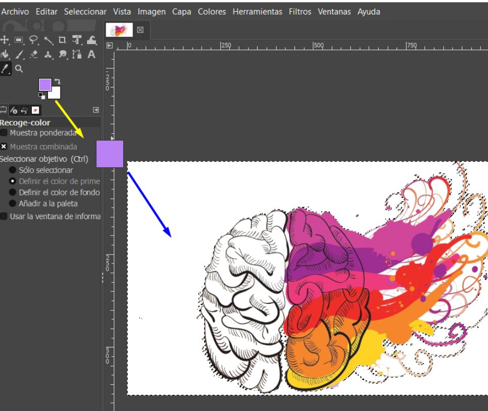
As you can see, the image has been successfully vectorized, with the background removed. We now have the flexibility to change colors and improve the design or image quality according to our needs. The Contiguous Color Selection tool demonstrates its versatility in this process.


Undoubtedly, GIMP is an exceptional tool that simplifies and speeds up the image vectorization and enhancement process. After having used it, I have no hesitation in recommending its use to more people. My experience with this software has been truly enriching.
It is a type of graphic representation composed of mathematically defined geometric shapes, such as lines, curves and polygons. Instead of storing information about the individual pixels that make up the image, a vector image describes the spatial relationships between these geometric elements. This allows the image to be scalable without loss of quality, as elements can be resized and edited without introducing artifacts or distortions, making them ideal for illustrations, logos, diagrams and other graphics where precision and scalability are important.
Inkscape is an open source graphic design software that focuses on creating scalable vector graphics. With a friendly interface and advanced drawing features, it allows users to create precise and complex illustrations. It offers tools for editing nodes and paths, supports several standard file formats, and allows customization through extensions. In addition, being open source, it is free and promotes collaboration and community development.
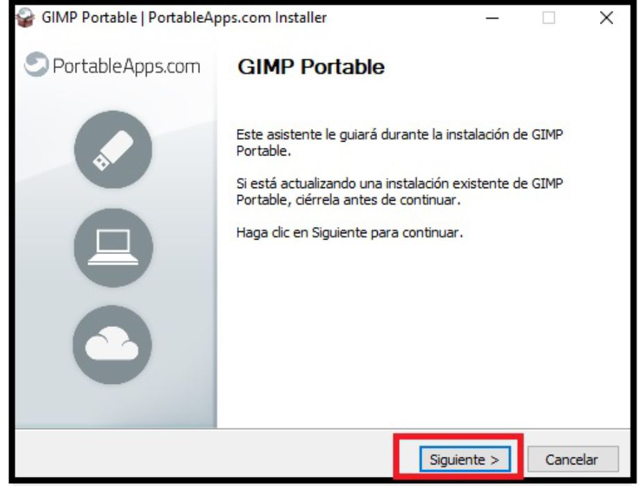
Installing Inkscape is simple and does not require complicated steps. Simply click 'Next' several times until the process is complete, and then run the program with a simple click.
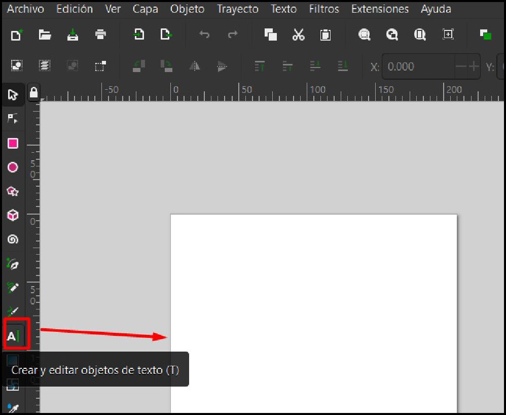
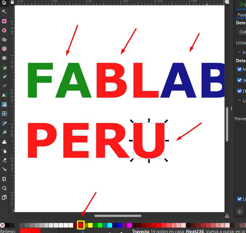
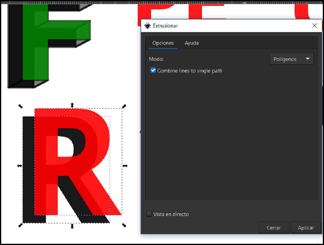
In the Inkscape environment, we have a variety of tools for working with vectors. We are going to create a 3D image from 2D letters.
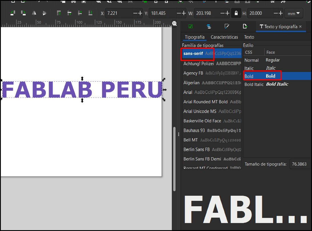
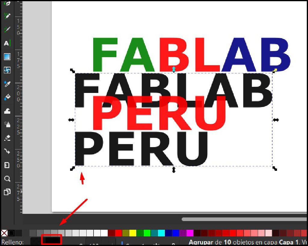
The next step is to ungroup the letters and change the colors to be able to make individual modifications. Later make a duplicate and change the color to black to follow the sequence and have the 3D
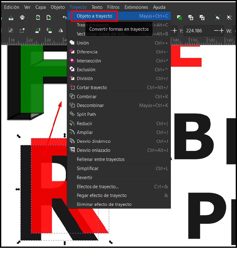
The next step is to select the letter "R" and apply the colors red and black to create a three-dimensional illusion and work with it. Then, on the toolbar, we select "Path" to have our vector ready to modify. Later in the toolbar we select "Extensions" then "Generate from path" and finally "Struct"
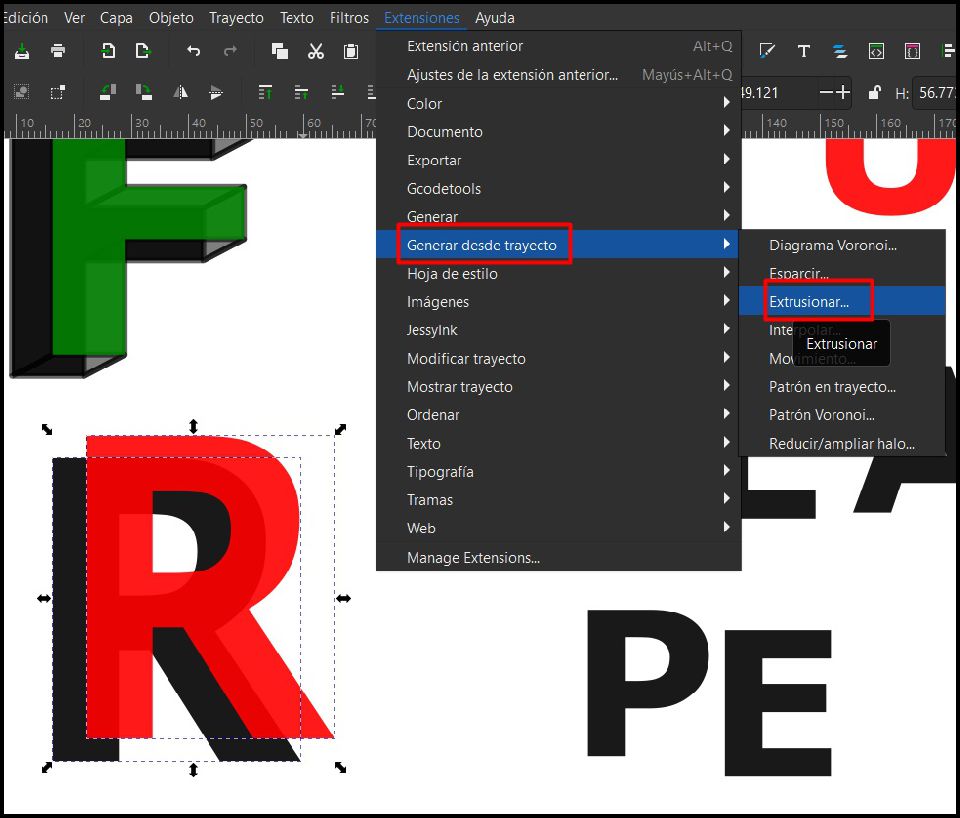
Finally, a new window will open where we will leave the "Combine lines" and polygons option checked, then we click on "OK"

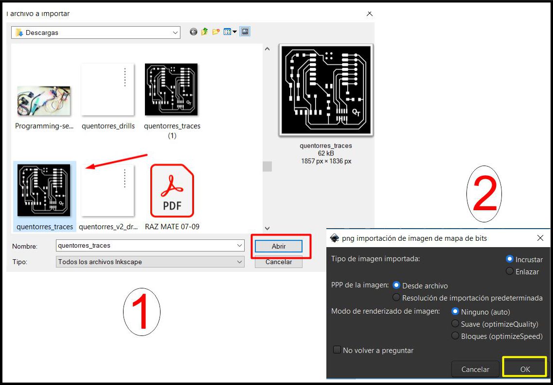
Once inside the work environment, the next step is to import the image that we want to vectorize. In my case, I am importing an image in PNG format of a plate and I show below. Resulting in a 3D image
Once the image has been imported, the next step is to go to the toolbar and select 'Path'. Subsequently, the 'Vectorize by Bitmap' option is chosen, which will generate a new image. Here, we mark the 'Invert Image' option and we can preview the already vectorized image.
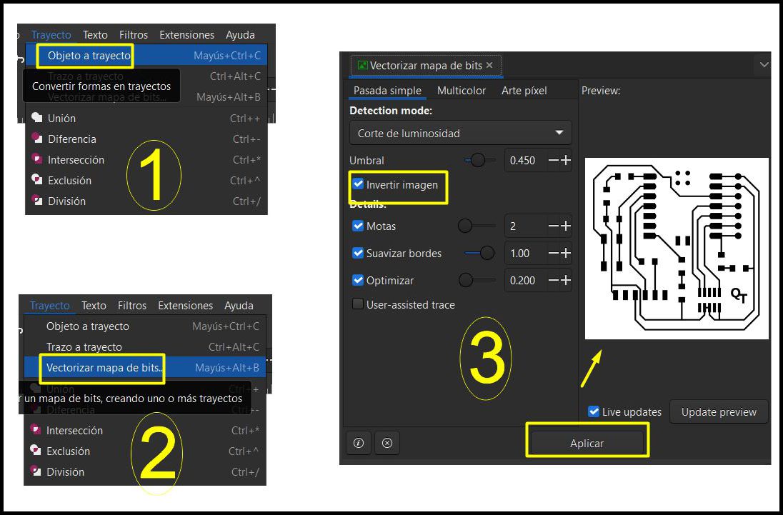
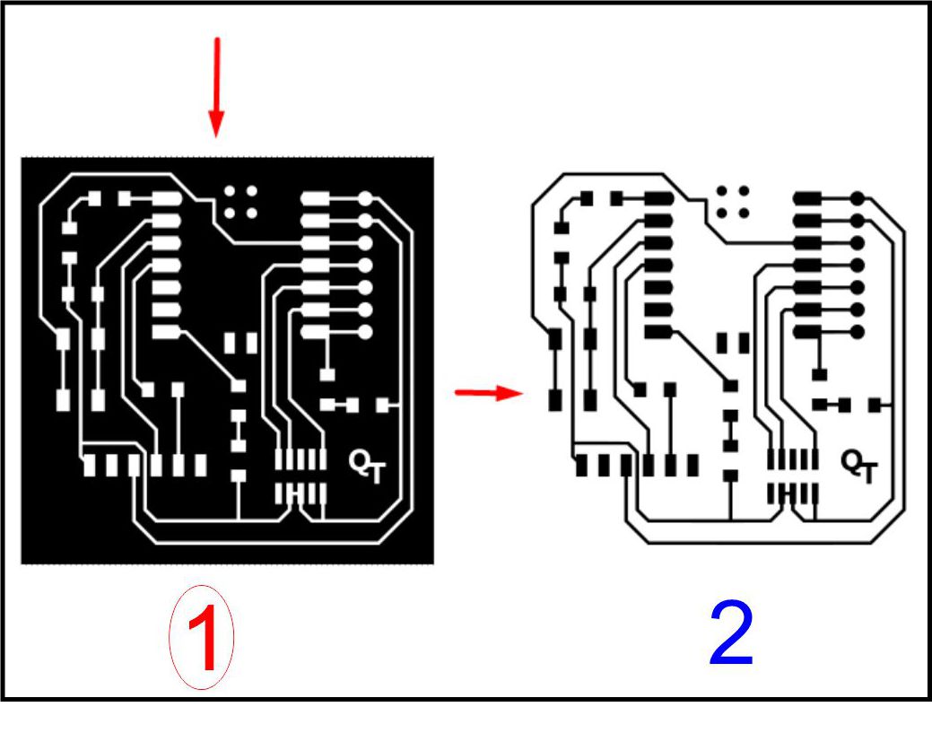
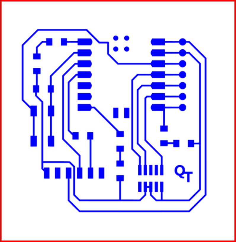
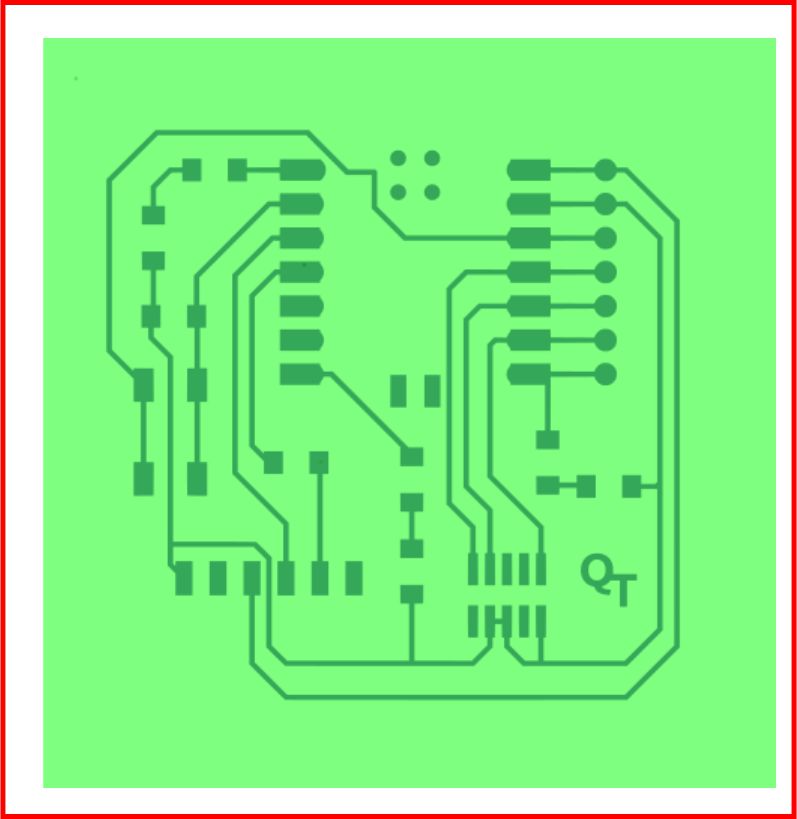
After vectorization and removal of the background, we have the possibility of modifying the appearance of the image. We can change the color of the tracks, as well as add a different background, such as simulating a printed circuit board (PCB).
Undoubtedly, Inkscape is another essential software that should be on your computer. It is highly recommended due to its ease of use; I firmly believe that anyone can learn to use it.
3D work in SolidWorks involves the design and modeling of three-dimensional components and systems using SolidWorks CAD software. This includes creating individual parts, assembling components, analyzing and simulating, generating technical documentation, and viewing rendered models.
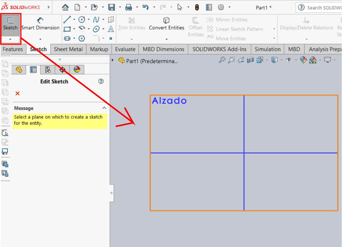
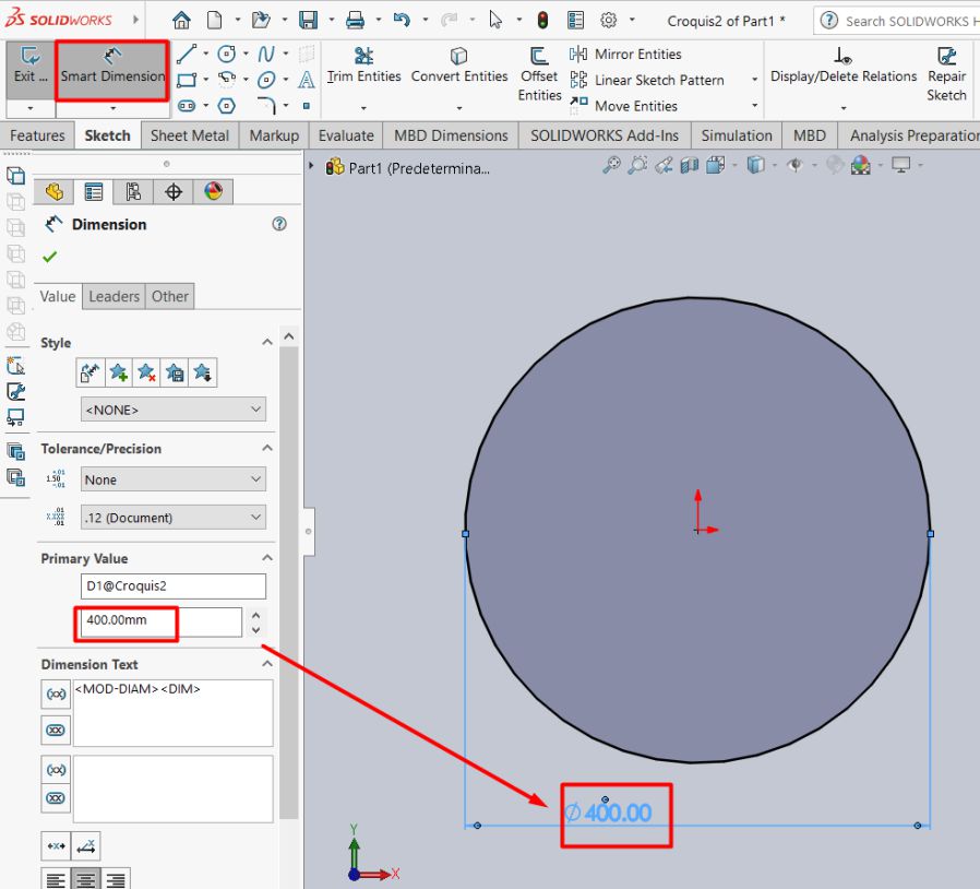
Within the Solidworks environment, access the “Sketch” tab. Select the plane you want to work on and then choose the circle drawing tool. Later, add a dimension to define the size of the circle. In this case, set the dimension to 40 cm.
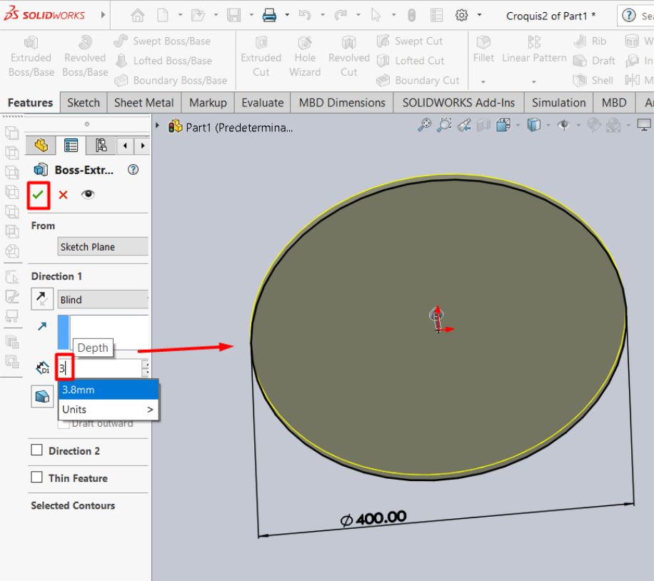
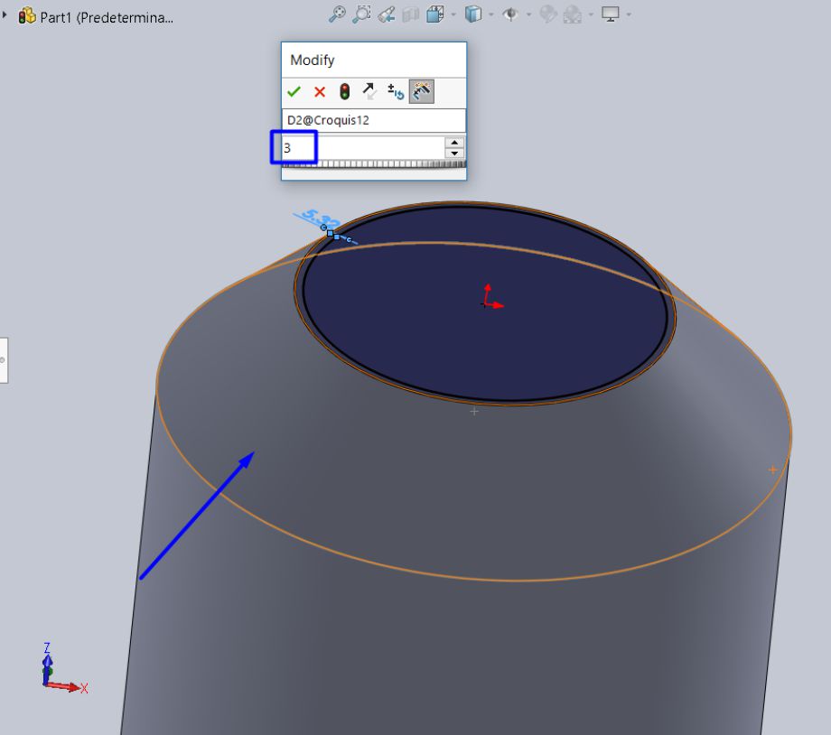
Once the circle for the tank platform has been defined, we proceed to create another inner circle with a thickness of 3 mm with respect to the outer edge. Then, using this sketch as a base, we extrude to obtain the shape of the tank.
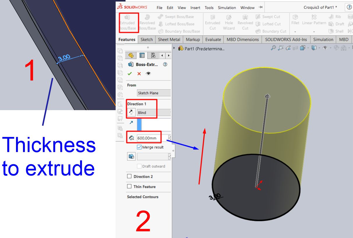
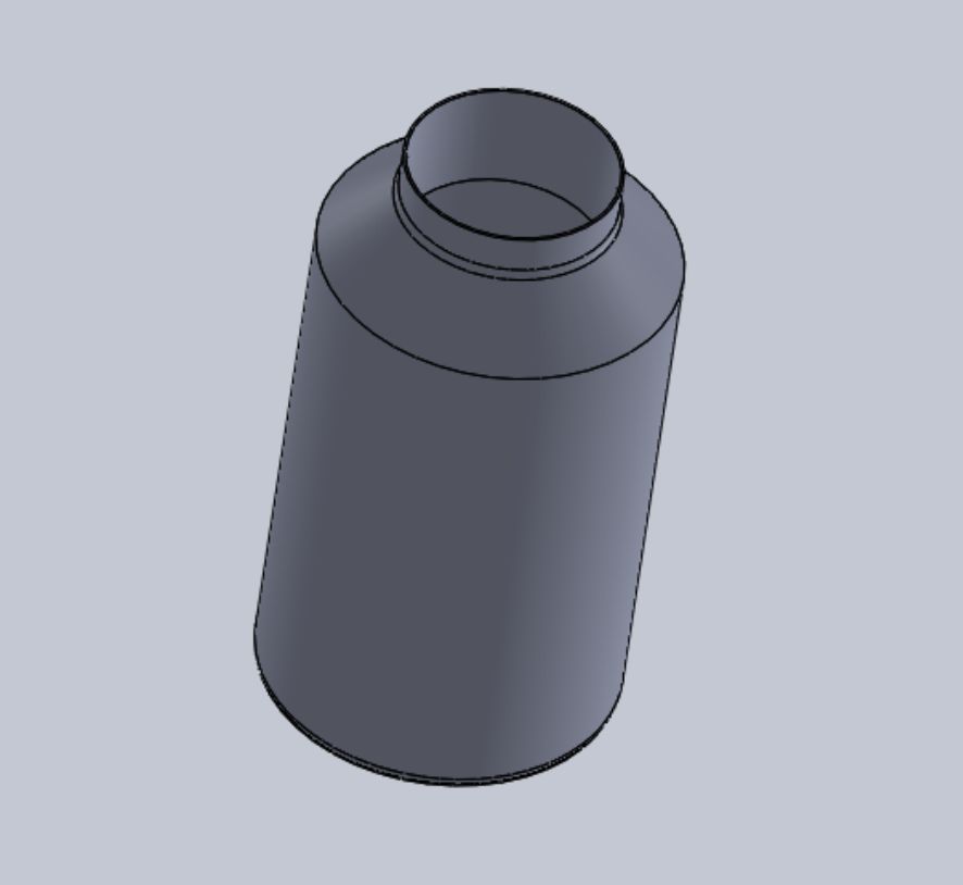
The next step is to carry out the extrusion at a 45 degree angle, followed by another perpendicular extrusion, in order to obtain the shape of a real tank.
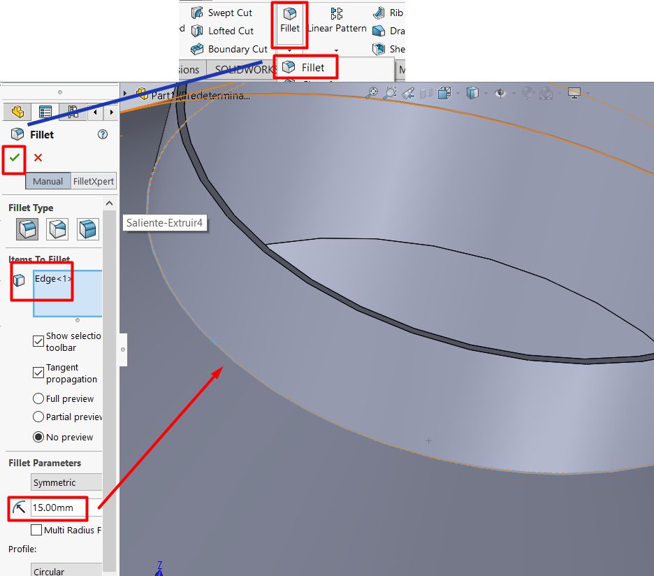
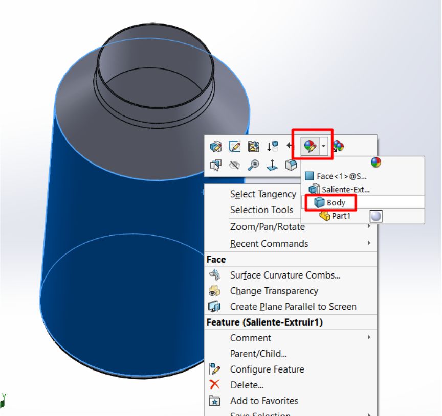
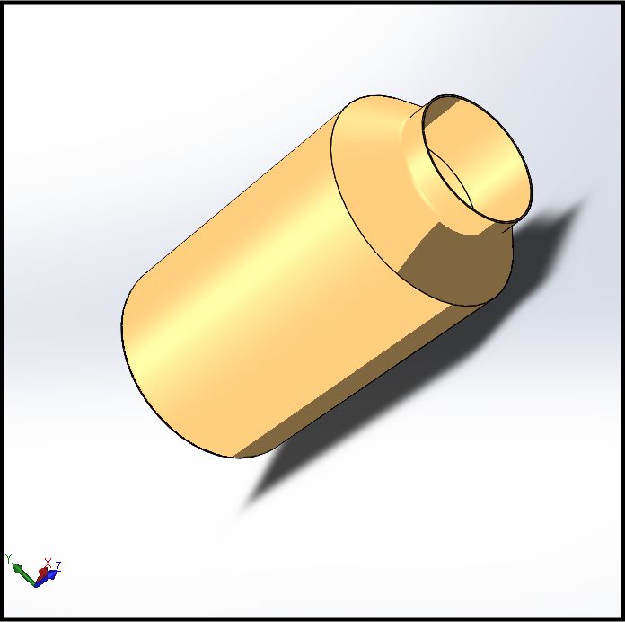
Una vez que hemos obtenido el sólido con la forma de un tanque, el siguiente paso es proceder con el renderizado para dotarlo de una apariencia realista, incluyendo todos sus detalles.
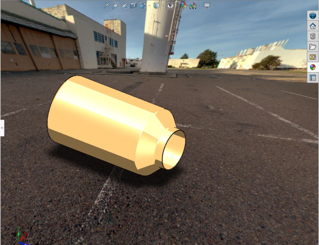
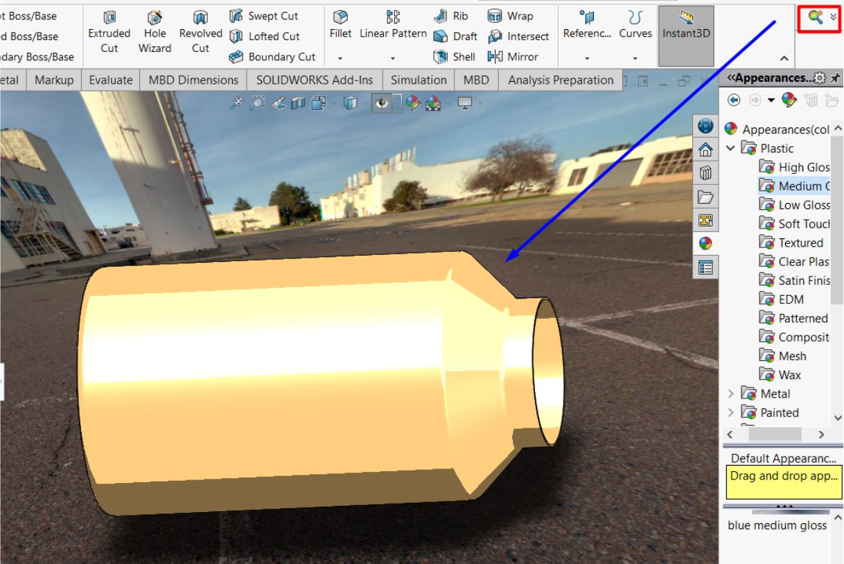
As we progress, we can see how the object takes on a more realistic appearance. In this case, I have colored it in a gold tone and placed it in an environment that simulates reality.
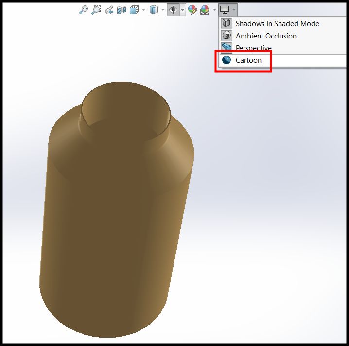
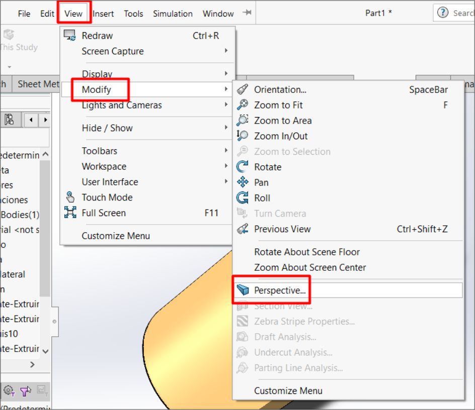
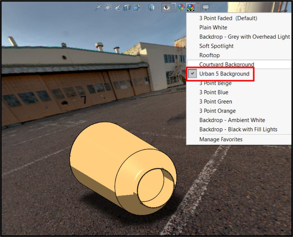
As you can see, we have set up a realistic environment by selecting a perspective view and an urban style.
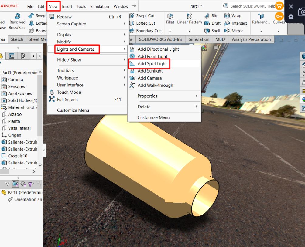
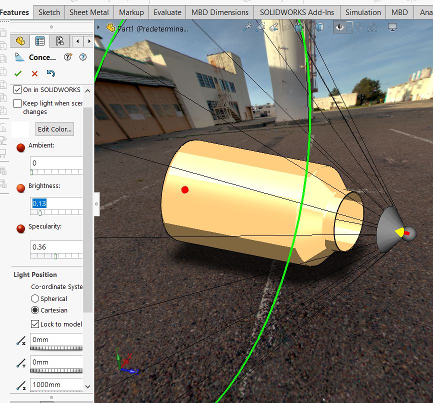
As a last step, we can still enhance the effect by adding more light and focusing it specifically on the design. This will further highlight the details and features of the design, providing a more powerful and attractive visual impact.
Basic steps to perform a simulation in SolidWorks.
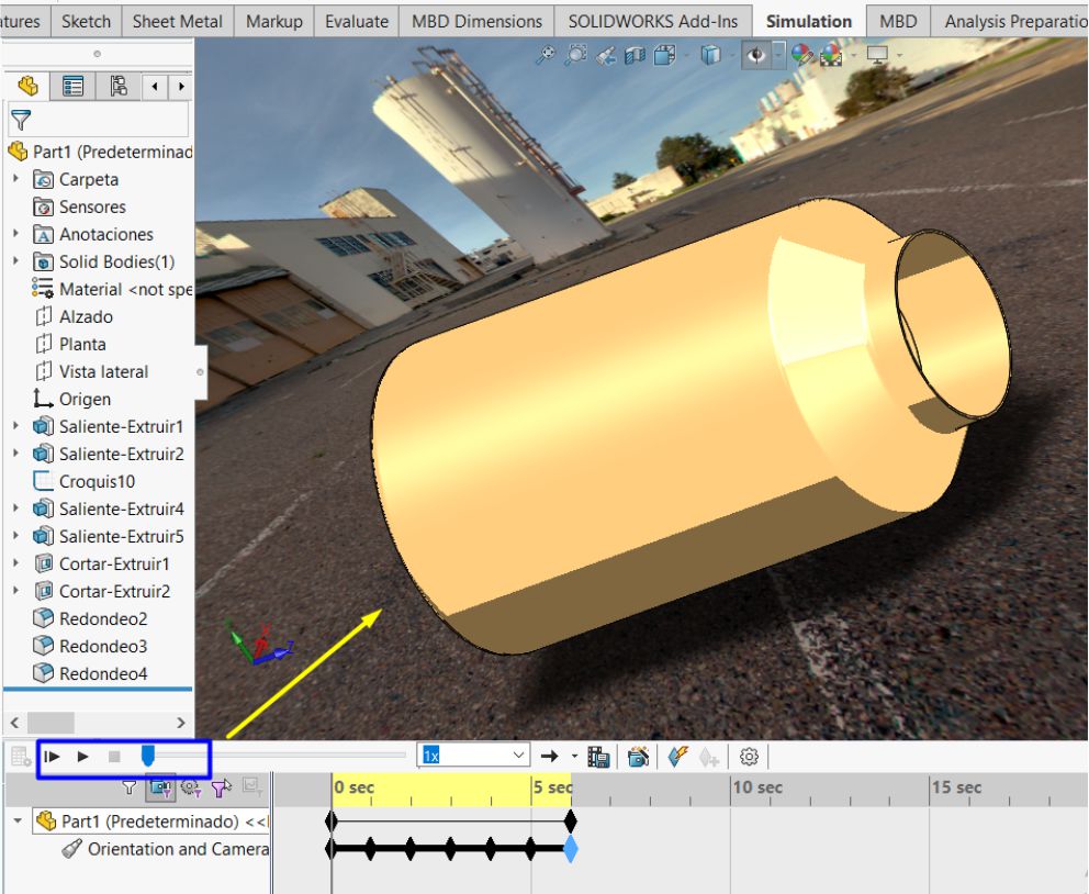
With the solid already designed and rendered, the next step is to perform a simulation. To do this, we select the simulation tool in the top toolbar, as shown in the attached figure.
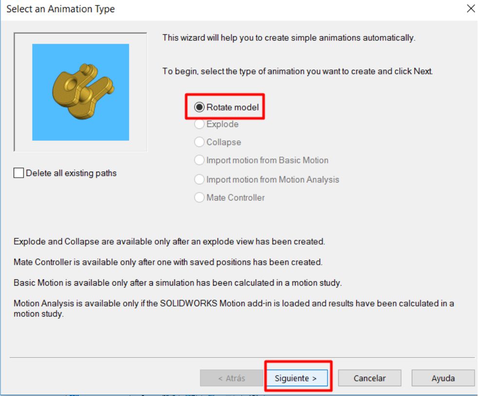
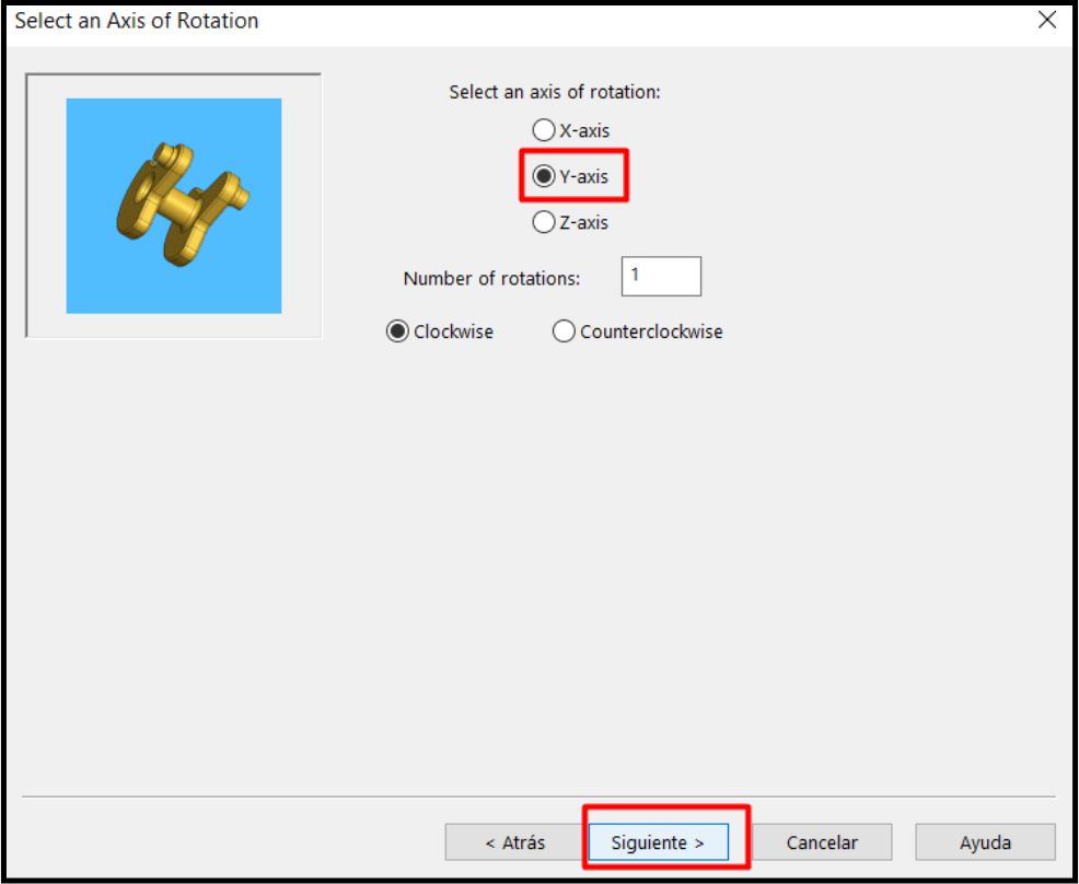
Afterwards, we will be asked for the type of simulation we want to perform. In this case, we will choose the option to rotate the model and we will specify in which axis we want to perform this movement.
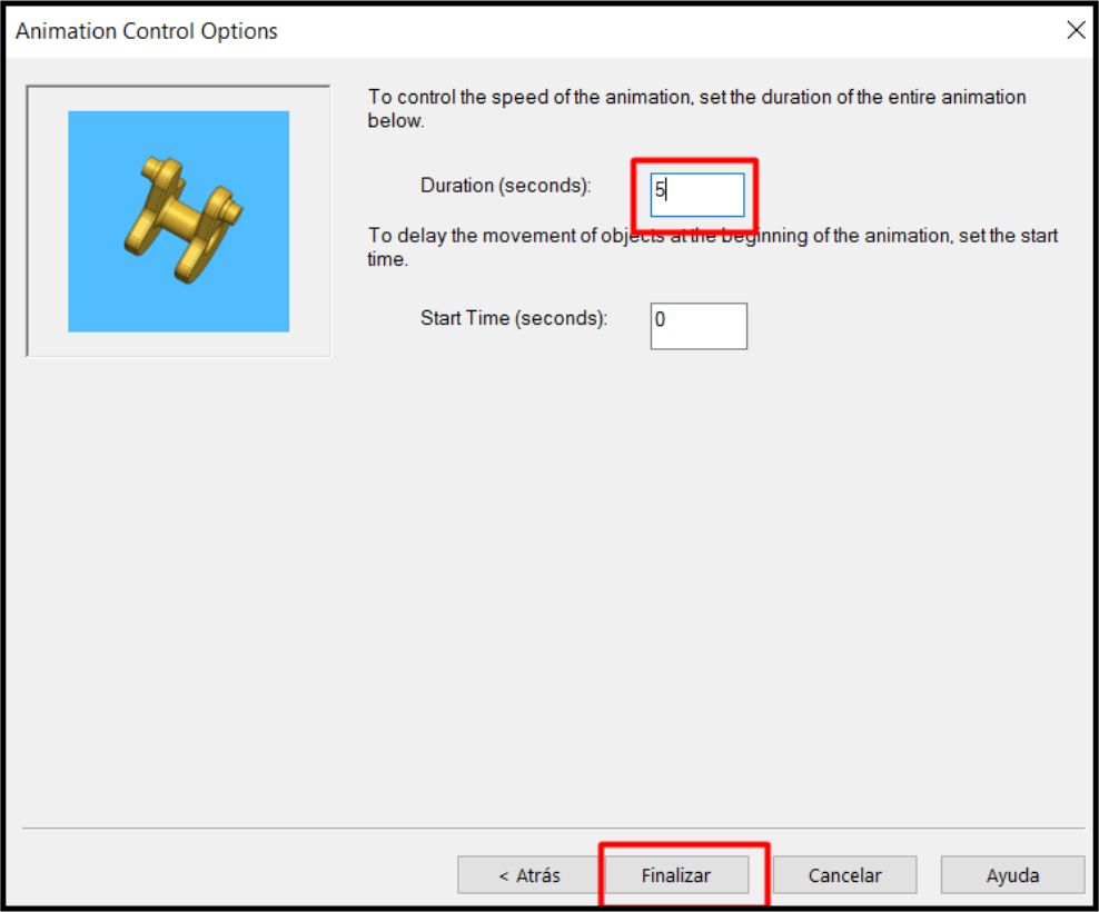
As a last step, we proceed to define the simulation time. In this particular case, I have set a time of 5 seconds. You can see this detailed process in the attached video
I used Blender software to design the glass pond. This will allow me to compare the results and capabilities between Blender and SolidWorks, enriching the development of my project.
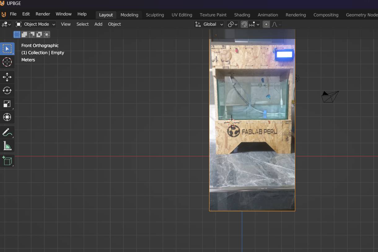
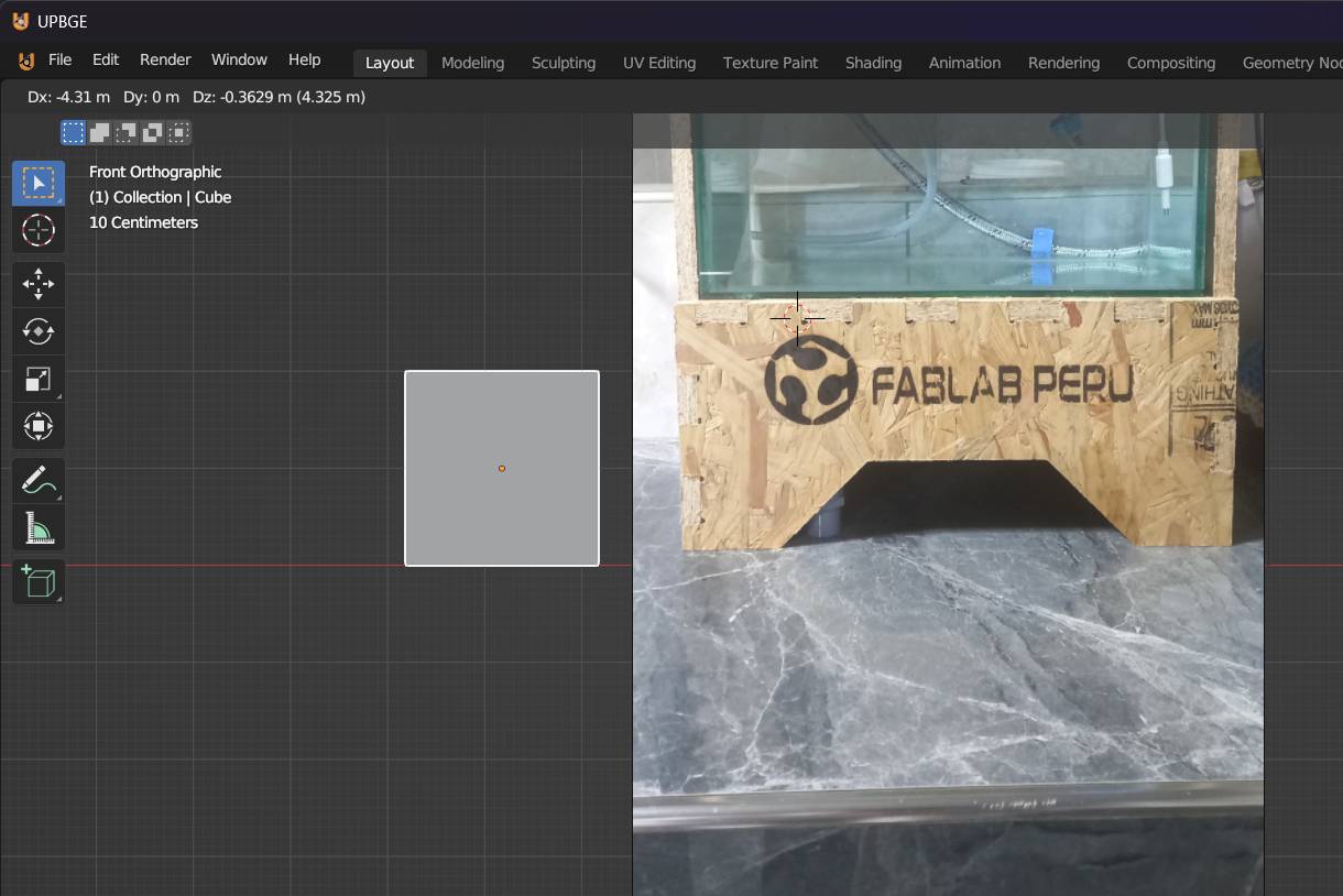
Below I will show the process step by step. First, a blank sheet of paper opens in the software. Then, a reference image, in my case, the pond design, is imported to have a visual guide while I work.
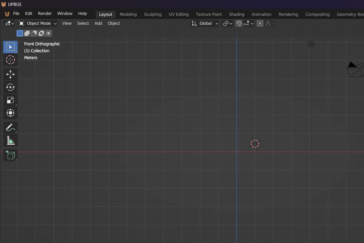
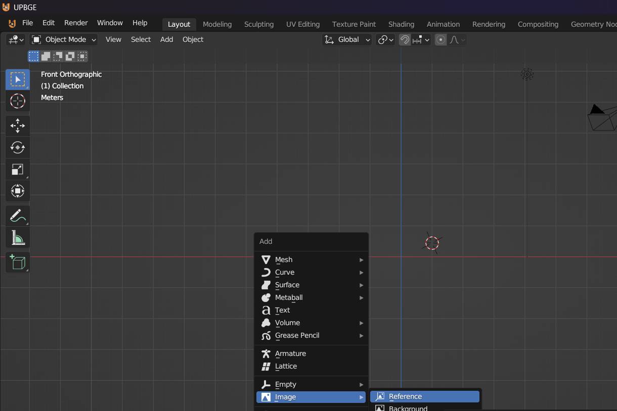
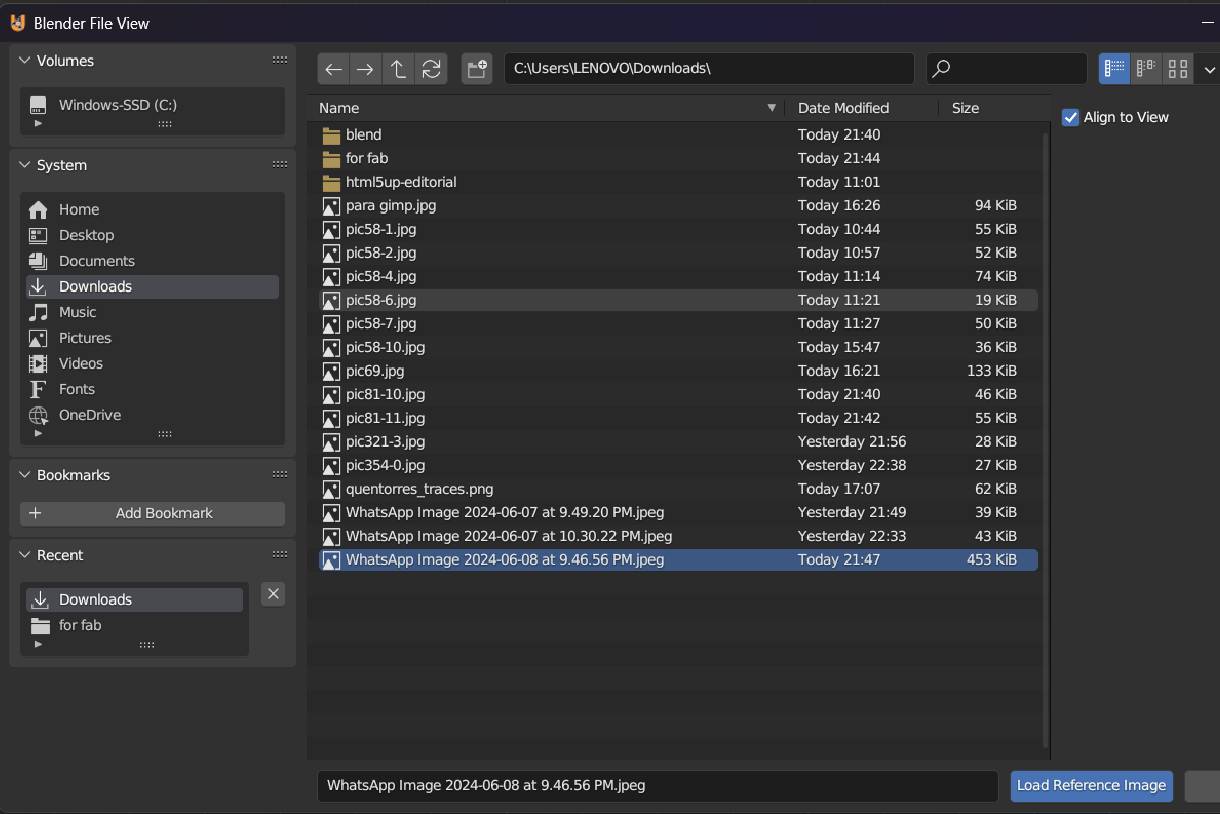
In my case, the reference image is from the project and is stored on my computer. To import it, we first press the Shift + A keys, which displays a list of options. In that list, we choose 'Image' and then select the image from the folder where it is hosted
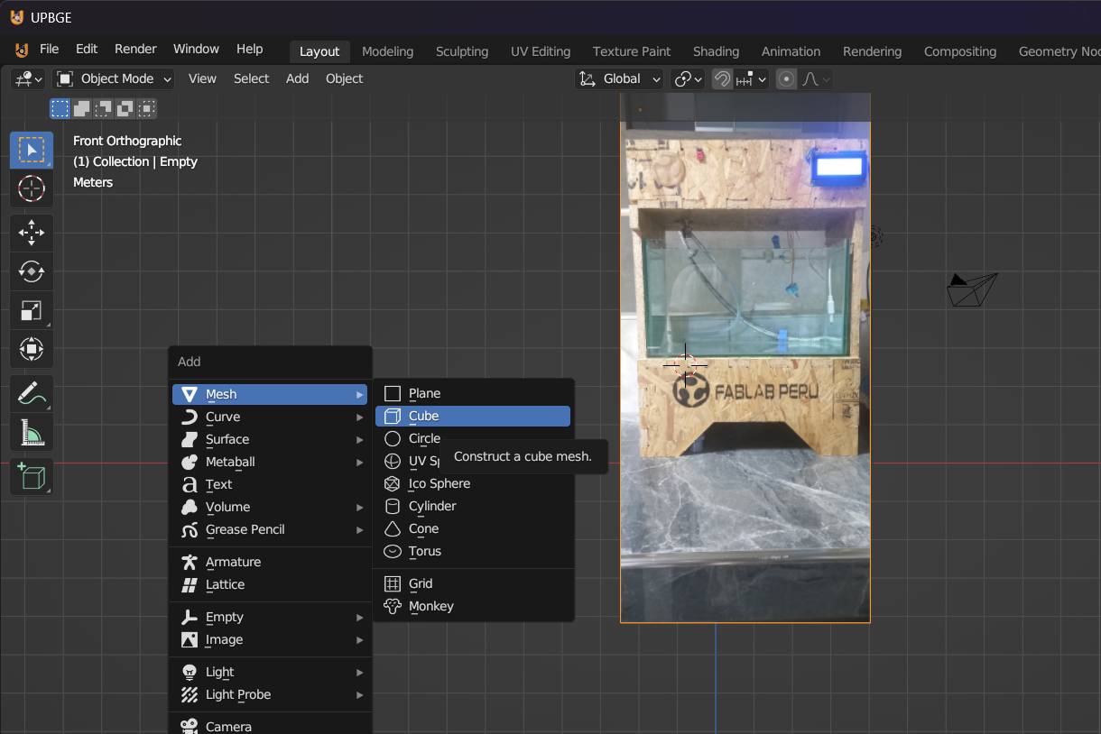
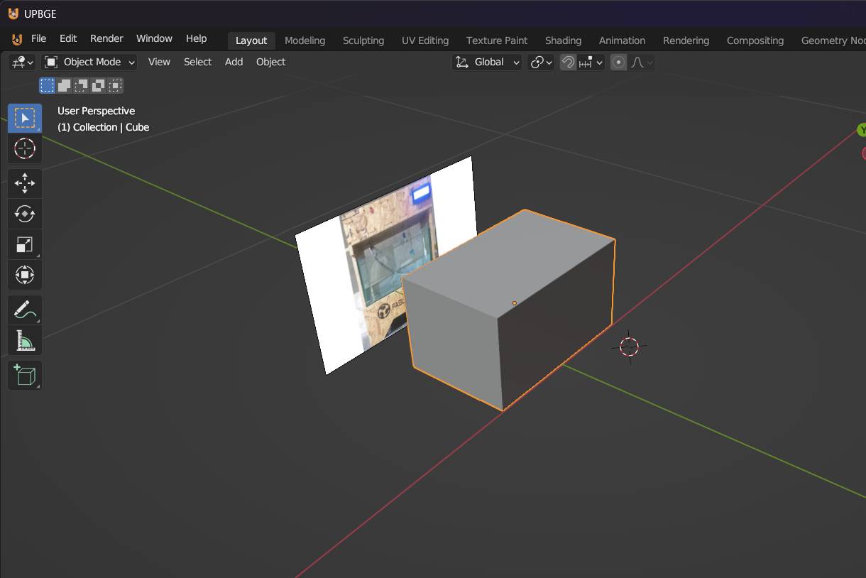
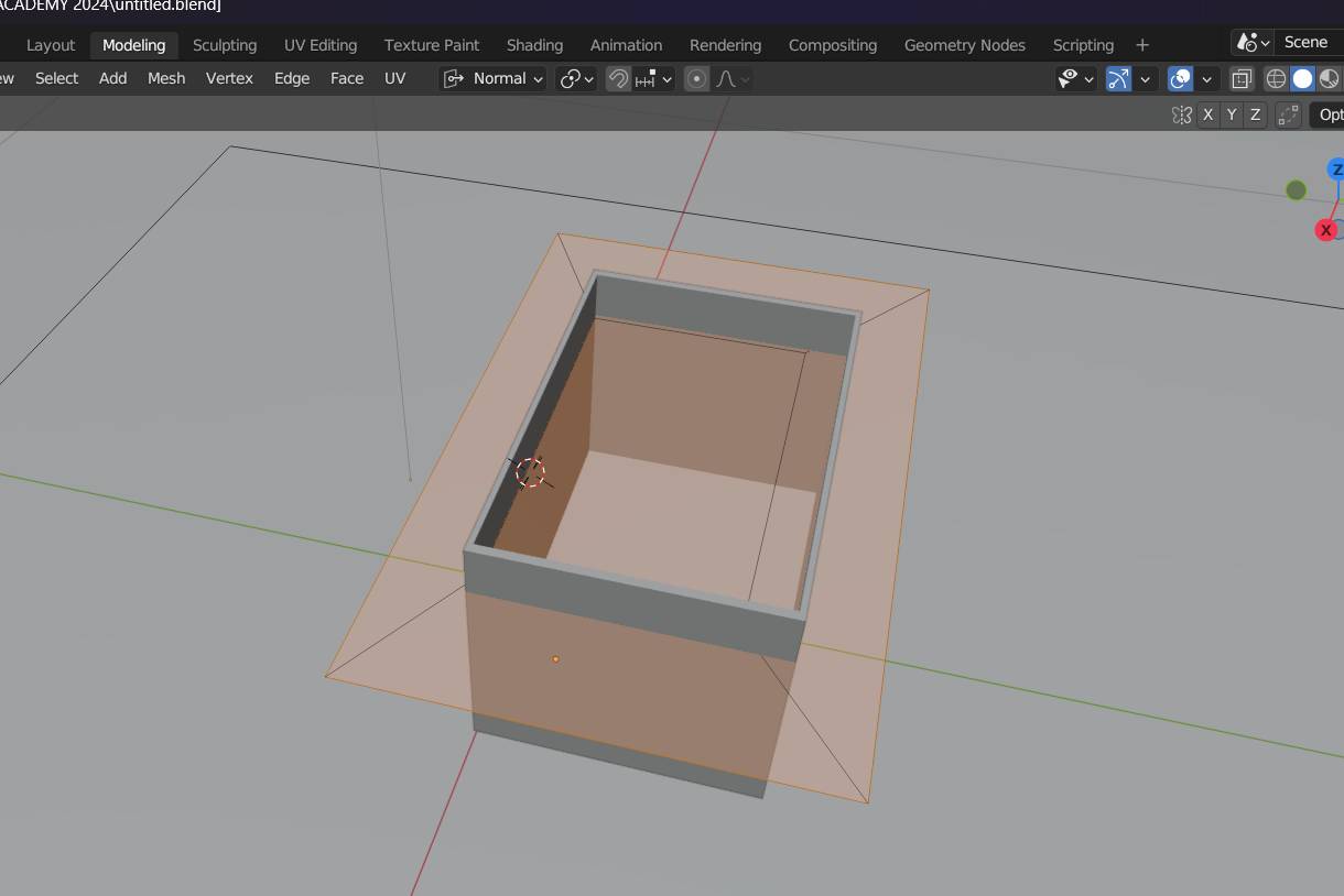
After importing the reference image, we import a cube. To do this, we press Shift + A again, select 'Mesh' from the drop-down list, and then choose 'Cube'. This will add a cube to our workspace.
Once the cube is in the workspace, we scale it according to the measurements of the reference image using the keys S + X to scale on the X axis, and S + Y to scale on the Y axis. To move the cube, we use the keys G + and E + Z to move it in the respective directions.
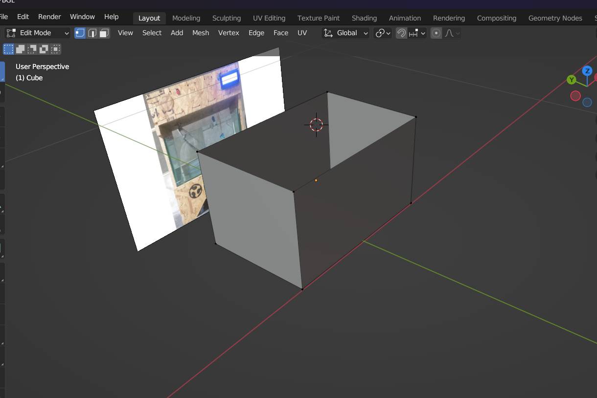
Next, we remove one of the faces of the cube, in this case, the top. Immediately, we adjust the thickness of the walls to 6 mm. Next, we constructed parallel planes to represent the walls of the tank. As we move forward, you can see how the cube begins to take the shape of a cubic glass tank.
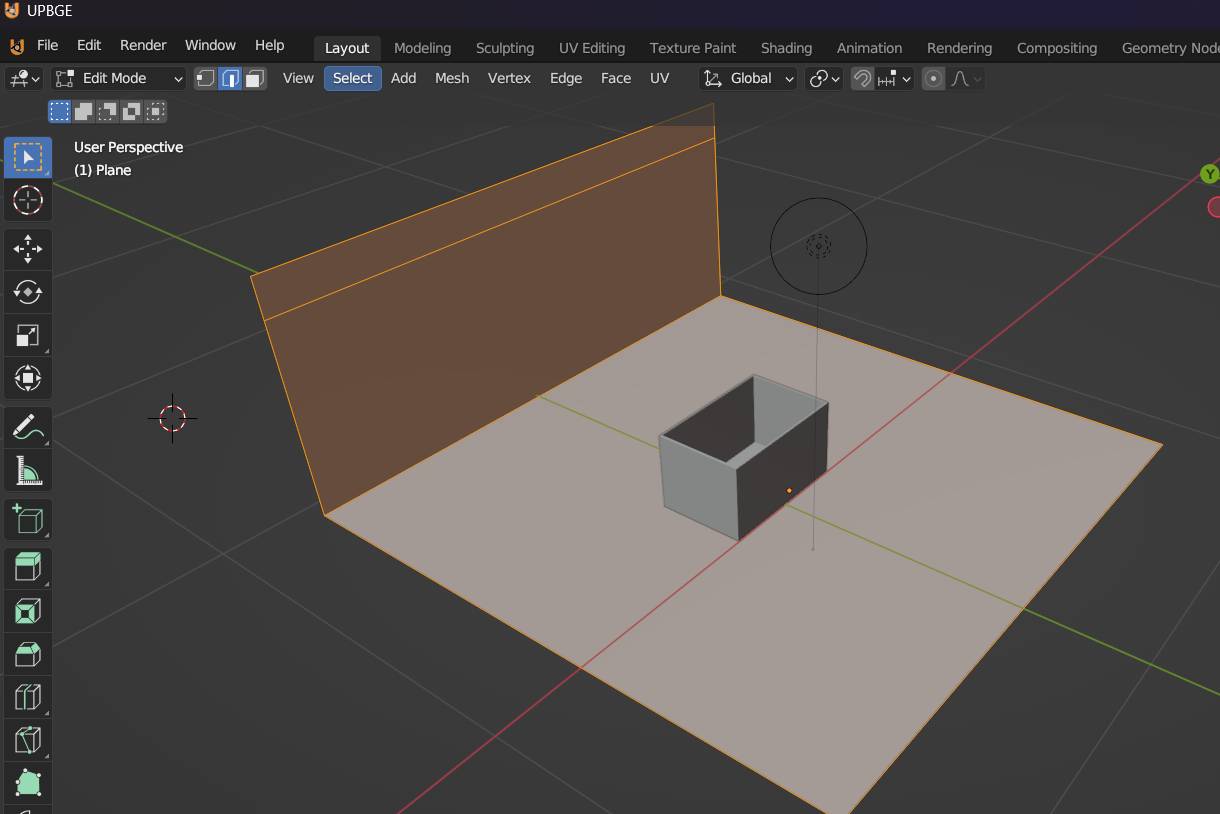
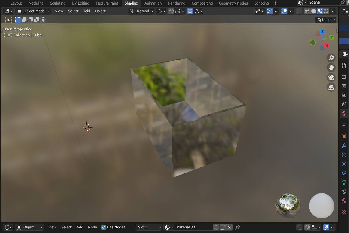
As a last step to complete the design of the small tank, we proceed to render it. Before doing so, we select the type of material and choose 'glass' to give it the right look. Once this is done, we render the model and we can see the tank in its final form.
In summary, working with the aforementioned software has been a great experience. However, I realize that I still need to get better at using Blender, as I have seen impressive designs made with this software. It is essential for me to experiment more with Blender, since it is open source, unlike other programs like SolidWorks. I have worked well with SolidWorks, but as I mentioned, I need to practice more with Blender to learn and become proficient. I am sure that I will succeed as I have installed this software on my computer and it is just a matter of practice.
As for Inkscape and GIMP, they have also positively surprised me. These programs offer a wide variety of useful tools for tasks such as vectorization and background removal, which is very useful for my projects.
3. RENDER Tank.jpg
3. Tank design.SLDPRT
4. Prototype assembly.SLDASM
4. GIMP-Colored Brain.xcf
4. Inkscape-fablab 3D.svg
4. Inkscape-quentorres_traces.svg
4. Blender-glass pond.blend
Development of custom electronic boards with CNC Router.
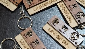
Development of personalized keychains and ornaments with CNC Laser.
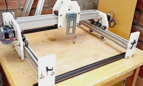
Development of custom machines "Desktop CNC Laser.
Huánuco is a Peruvian city, capital of the district, province and department of the same name in the north-central area of the country. The city has a population of 235,529 inhabitants. .